How to build an outdoor Single Channel LoRaWAN Gateway based on Heltec ESP32 LoRa dev board
Two years ago I began my adventure in the Wireless Sensors Network (WSN) world and, among the main existing wireless protocols, one of the most widely used is, of course, LoRaWAN. In this tutorial I going to show you how to build an outdoor Single Channel LoRaWAN Gateway based on one of the cheapest ESP32 development board available on internet: the Heltec ESP32 LoRa V2 dev board.
A Single Channel LoRaWAN Gateway based on an ESP32 dev board is a very affordable starting point to begin LoRaWAN prototyping without the need to buy a full LoRaWAN Gateway, which has eight working channels and a more complex transceiver, thus an higher cost (but you’ll need it once you’ll work with multiple LoRaWAN end nodes, given the Single Channel solution limitations).
First, I’m going to explain a bit, what is LoRaWAN (HERE a detailed explanation) and what is the difference with LoRa. Then, I’m going to explain step by step what you need to create a Single Channel LoRaWAN Gateway to place outdoor, maybe on a roof like mine, because if you will use LoRaWAN, you’ll use it for Long Range Communication between one or more end nodes and the gateway, so, the higher you place it, the wider the radius of coverage will be. Finally, I’ll show you some range tests and explain which are the limitations of such system.
Table of Contents
A Single Channel LoRaWAN Gateway based on Heltec ESP32 LoRa dev board
What is LoRaWAN?
I already answered in a detailed way to this question in a dedicated article (you can find it HERE). However, here you are a short description: LoRaWAN is a Long Range communication protocol often used to create Low Power Wide Area Networks (LPWANs) with an operating range that goes from 300 meters up to 10 kilometres. It is based on LoRa modulation while the Medium Access Control (MAC) layer is an open network architecture regulated by the LoRa Alliance. LoRaWAN end nodes can also be classified into three categories: Class A, B, and C. All LoRaWAN devices must implement Class A, whereas Class B and C are extensions of Class A devices. These classes, defines the behaviour about downlink packets from gateways to end nodes. Usually LoRaWAN gateways acts as Class C devices, since they are constantly listening for incoming transmission.
In order to transmit and receive data over LoRaWAN network, LoRaWAN end nodes must be registered and enabled on the Application Server provider, which manages the open network gateways. That’s why, in the last part of this tutorial, we will register our gateway on the things Network.
Single Channel LoRaWAN Gateway Requirements
We need many components plus the ESP32 with Semtech SX1276 LoRa modem development board. In my case, I decided to use the Heltec ESP32 LoRa V2 board based on the ESP32 microcontroller. There are two version of it: the first one has a SX1276 LoRa modem and is suitable for 868/915 MHz EU/US LoRaWAN carriers, while the second one is based on the Semtech SX1278 modem and is suitable for 433 MHZ CN bandwidth. So be sure to buy the right one based on your development board connector. Finally, You’ll need a pole where to fix the IP65 waterproof box, a power supply able to deliver up to 1A at 5 Volt through a typical USB connector, and a USB-to-microUSB cable (at least five meters) to deliver power to the board placed on the roof while keeping the power supply in a dry and secure environment. You will also need many screws to fix the IP65 box to the pole. I also used some Lego bricks to fix the board inside the box … but you can use different solutions.
Summarising, you need:
- one ESP32 development board with a built-in LoRa modem and antenna connector;
- one external antenna with the right connector and length for your frequency and dev board;
- an IP65 box;
- a pole;
- a 5 Volt 1A USB power supply;
- a USB-to-microUSB cable, with a length of at least 5 meters, depending also on your installation;
- something to fix the board inside the box;
- many screws and rods to fix the box to the pole.
Total cost should be around 30-35$.
The ESP32 SoC
ESP32 is a cheap and low power SoC which integrates an IEEE 802.11 a/b/g/n and both Bluetooth Classic and BLE IEEE 802.15.1 radio equipments. It is widely used for many industrial applications and also IoT products, since the whole SoC with a 2.4 GHz Printed Circuit Board (PCB) antenna has a package size of seven for seven millimetres and a low price. Also, many IoT manufacturers have released different kind of development boards based on ESP32 SoC, allowing developers to chose the right solution based on their needs. In fact, different boards could have various PCB layouts with pre-installed sensors, relays, RGB LED, display, external antennas connectors, LoRa modem (such as the Heltec ESP32 Lora V2, used in this project), GPS receivers, batteries and even cameras for almost any application. Its high integration also, ensures that it is reliable and resistant to extreme operating temperatures (between -40°C and +85°C), making it suitable for applications in harsh environments. ESP32 SoC is made by the Chinese company Espressif Systems, and it is the successor of the Wi-Fi-only ESP8266 SoC, which i have used in another project. It integrates a Tensilica Xtensa LX6 dual-core 32-bit CPU whit a clock that can achieve up to 240 MHz. There is also an Ultra Low Power (ULP) co-processor and a Real Time Clock (RTC) to enable deep-sleep functionalities, useful for battery powered devices with long stand-by times. Then there are 520 KB of SRAM, followed by 448 KB of ROM for booting and core functions, and up to 16 MB of embedded ash memory, which is plenty for almost any end node implementation. The SoC also integrates all the radio components needed for the functioning, since clock generator, receiver, transmitter, balun and antenna, are all inside the same package, making it a ready to use solution. Full Wi-Fi and Bluetooth protocol stack are also supported, making it easer to develop application based on these interfaces. The whole chip is manufactured by TSMC foundries using a 40 nanometres process, which ensures a good trade-off between costs and integration, thus low power consumption. All the SoC integrated components are shown in the following figure.
Hardware setup: connecting the Heltec ESP32 to the antenna
In this project there isn’t much to do on the hardware side. We just have to connect the development board – in this case the Heltec ESp32 LoRa V2 – to the antenna using the bundled SMA connector. I decided to replace the bundled antenna with a “bigger one”, in order to achieve an higher gain (5 dBi). Also, the antenna adopted can be tilted, so that I can place it in a vertical position without waterproofing issues. Once this operation has been done, we can go go to the software flashing. It’s strongly suggested to use the Heltec ESP32 LoRa with the antenna connected, otherwise you can burn the built-in modem. This applies also for any other external antenna device, so be careful!
Software setup: compile and flash the LoRaWAN Single Channel Gateway implementation of the Heltec ESP32
At this point, we have to work on the software part. I use the Arduino IDE to program my ESP32 and 8266 boards. However, you can use any other IDE you want. If you decide to use Arduino IDE, be sure to import the right libraries and COM ports driver. You can check this tutorial.
Now we have to simply compile and flash the firmware to our LoRaWAN ESP32 development board. Initially, we have to download the LoRaWAN Single Channel Gateway implementation for ESP32 and Semtech-based dev boards, like the one used in this tutorial. As already stated, I’m not the developer of the LoRaWAN implementation, so I’ll link the original author (Maarten Westenberg) of the code, where you will also find the updated version of the code: GitHub repository.
Clone or download the whole repository, decompress it and go to the “src” folder, where you will find the source code of the LoRaWAN Single Channel Gateway implementation for any ESP32 board with a Semtech Lora modem.
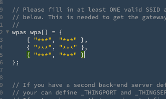
There are many files in this folder. Among them, we have to modify at least the “configNode.h” file, where we have to place our Wi-Fi network SSID and password. You can place more than one Wi-Fi SSID, so that if it can’t be found, the LoRaWAN Gateway will fall back on the second or third Wi-Fi network in the list. If you are using a different ESP32 development board, you also have to change your hardware configuration inside the “configGway.h” file, where you have to specify your pin configuration and the OLED display installed on your development board. You can also act on other parameters such as Spreading Factor, Channels, Carrier frequency based on your country (EU is 868 MHz, USA is 915 MHz, pay attention to this parameter!) and so on, but in my case, I only had to set the OLED display to 1, which is suitable for the Heltec ESp32 LoRa V2 board.
Safe the configurations and then open with your Arduino IDE the “ESP-sc-gway.ino” file. A pletora of additional files will be opened inside the IDE, but you don’t have to touch them. Now, if you have already installed all the ESP32 libraries, you can now import the additional libraries which have been downloaded together with the source code from the repository. You just have to import them using the “Sketch menu option” inside Arduino IDE. Select all the libraries inside the downloaded “lib” folder and import them. Now you should be able to compile the firmware without any dependency error.
To do this, you have to select your ESP32 LoRa development board inside “Tools” menu inside Arduino IDE. Then, connect it to your computer using the right cable and select from “Tools” menu the right port. At this point, you can press the compile and flash button. If all goes well, your ESP32 board will restart after a couple of minutes as a LoRaWAN Single Channel Gateway. You can monitor it both using the serial monitor function or directly from your browser (of course, both the PC and the GW should be connected to the same network) by typing the device IP in your browser URL bar. The IP is printed on the serial monitor console each time the Gateway reboots, or you can look for it using many network tools or by checking your DHCP server.
I also have to say that I made some changes in the original code, because I implemented a different kind of OTA update and an additional DHT11 sensor, in order to measure the temperature over the roof of my house. Finally, I overcome the maximum payload limit of the received messages, which is, by default, set to 64 bytes, replacing the HEX value to the 184 bytes equivalent, since over this value the system seems to truncate the messages.
Software setup: LoRaWAN Single Channel Gateway web interface & settings
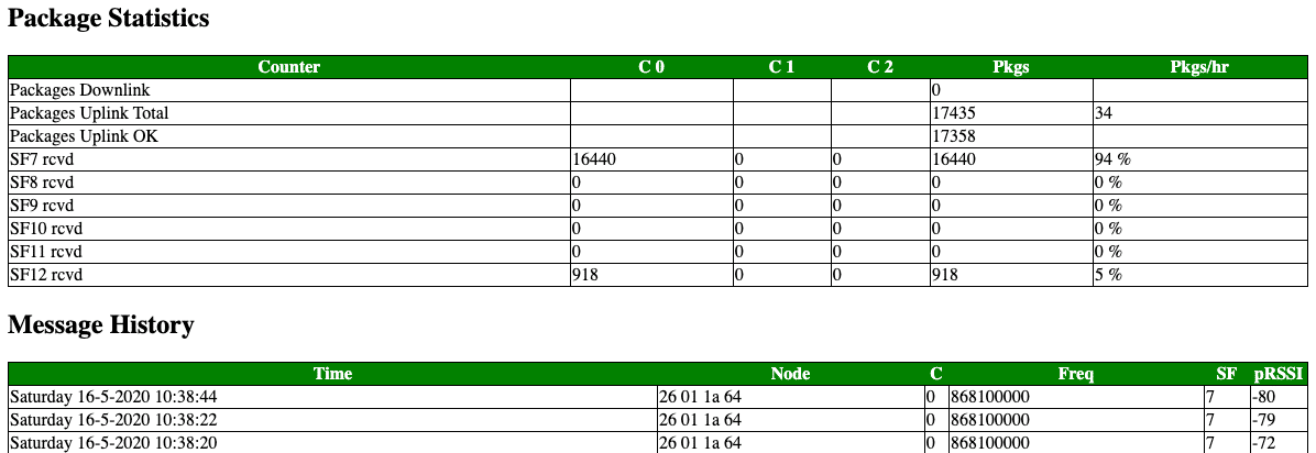
The LoRaWAN Single Channel Gateway comes with a rich and useful web server which can be accessed through the IP address of the device over the same LAN. The web server interface provides many useful information for debugging and statistics. For example, it is possible to see the last received message’s SF, device’s classes, RSSI, node identifier and other statistics, as visible below, which represents a portion of the default web server page.
In the same web page all the LoRaWAN Gateway parameters can be seen, such as the IP address of the device, the LoRaWAN router IP and URL, the connected Wi-Fi SSID and the GW ID, which is needed for the registration on The Things Network, as we’ll see later. There are also many information useful for system debugging, such as the number of Wi-Fi connection attempts and the available free memory. It is even possible to enable a logging system which can then be download through the web interface. The Web interface not only provides statistical tools, but also many controls, since there are buttons to enable/disable some features and to change GW settings. For example, it is possible to enable or disable Channel Activity Detection (CAD), needed for enabling the reception of messages with different Spreading Factor over the same channel.
Then, it is possible to manually change the channel form the default one or to setup an automatically frequency hopping to change the LoRaWAN channel among those available. Thus, it is possible to reset board statistics, change the debug level and I decided to add a button to reboot the Gateway remotely. All these remote control solution are mandatory in a context where the GW is not easily accessible, such as in my final installation, where the LoRaWAN ESP32 GW is placed over the roof of my house.
Software setup: the Things Network Gateway registration
If you want to use the developed system, you have one last easy step to do: register on The Things Network (TTN) and connect the Heltec ESP32 GW to it. In order to do this, simply go HERE.
TTN is a free to use network infrastructure with the goal to provide free LoRaWAN network coverage around the world. Thanks to its community, The Things Network is the biggest and most used LoRaWAN network, since there are more than 10’000 LoRaWAN Gateways around the world and about 108’000 community members. TTN provides a set of software tools which allows users to create their own LoRaWAN application or to simply setup a GW. Therefore, any LoRaWAN nodes (both GWs and end nodes) must be registered on TTN platform in order to operate correctly.
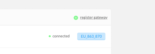
The developed LoRaWAN Heltec ESP32 GW can be easily registered on the network thought the console section, where the user simply has to add a new LoRaWAN Gateway by clicking on the “register device” label.
Then, you have to chose a name and the right parameters. You will also need one parameter, which is the Gateway ID and it is uniquely related to the LoRa modem onboard, so that each node has a unique ID. You can find it inside the LoRaWAN Web server interface under the voice “Gateway ID“, and it’s a 16 characters string. Put it into the right TTN field and complete the registration process, then your GW is ready to provide LoRaWAN connectivity to yours applications.
The final installation
If you arrived here, you can already use your LoRaWAN Single Channel Heltec ESP32 Gateway but … in order to reach better performances, there is one more thing to do: place it as high as you can. I know, it’s not a simple process but, thrust me, it is well worth, since it’s the only way to reach a coverage of more then 3-4 kilometres.
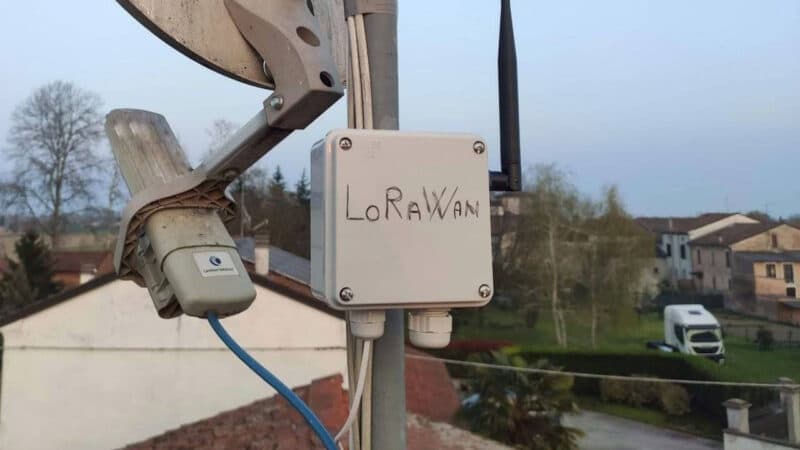
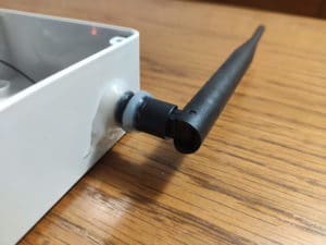
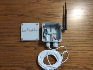
To do this, I placed the board inside an IP65 box, while the antenna has been placed and isolated on the side, in order to keep the system as waterproof as possible. Here below you can see some pictures of the system and some details of the IP65 adaptation.
In order to fix the board inside the box, I used some Lego bricks, and I finally placed the power cable on the bottom side, where it has been fixed. In the picture you can also see the DHT11 sensor located in a bottom hollow.
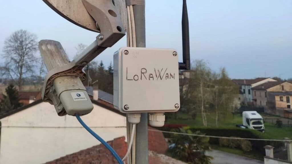
Finally, I placed it over the roof of my house, fixing it to the TV antenna pole, at about 14 meters height from the ground.
The system is up and it’s running since late February 2020 (yes, it survived a pandemic). It has seen snow, ice, frozen winds, heavy rains, hail (what a hail!) and many thunderstorms, but it’s up and it’s running flawlessly.
Closing thoughts: achieved operating ranges!
In this section I’ll briefly show you what kind of coverage I can reach with this system. I live in a very small town, with less than 700 inhabitants, so there are a few houses, mostly 2 or 3-floors houses, so there is any tall building between my LoRaWAN Single Channel gateway and the two final LoRaWAN end nodes I installed in the country side.
Using the lowest LoRa Spreading factor – SF7 -, I can easily cover one node (A in the picture) placed at 1.25 Km from the GW, across the “city”, and a second one (B in the picture) placed in the countryside behind my house ad 1.92 Km.
The first node is in Non Line-of-Sight (NLOS) setup, given the sub-urban environment with many buildings and trees between the two devices. The partial urban environment with its buildings limit the operating range of LoRaWAN communication, since the observed Received Signal Strength Indicator (RSSI) is near at the minimum acceptable level for SF7, with a mean value around -118 dBm. Therefore, only 83% of the messages are successfully received by the GW, but, for this kind of application (a weather station) it’s enough.
The second node is in an almost obstacles free environment, with a direct Line-of-Sight (LOS) between the two devices. the result is a “good” RSSI of about -115 dBm, which should allow a greater distance on such environment. That’s enough to reach a 98%+ correct packets reception, achieving a reliable Long Range communication.
Drawbacks
As stated in the introduction, this system is cheap, works well and can be used for two, three and even more LoRaWAN end nodes but … there are many limits. First of all, all the end nodes must use the same channel, so if you’re gonna send a lot of messages, you gonna have some collisions problems and lose them. Second, it’s not a fully compliant full LoRaWAN Gateway, because it has only one operating channel and because the uplink operations have some issues, since too many uplink messages makes my gateway reboot. Also, a gateway like this won’t really help the LoraWAN community, since it has only one channel, so please, consider a powerful and complete one once your prototyping is complete and you’re going to deploy your applications. Finally, there is another “serious” issue which explain why I decided to fix the system with a Spreading Factor equal to seven (SF7) to both the end nodes and the gateway itself. If you enable Channel Activity Detection (CAD), you will be able to receive messages with different SF on the same channel, but your sensitivity on chirps with higher spreading factor will decrease a lot, so the system performance for Long Range applications will be awful. That’s one of the reason I decide to keep the system fixed to SF7. However, you can fix the LoRaWAN gateway to SF9 of higher for longer distance applications, and you will easily reach 3-4 km (I can easily get 5 Km with SF12) and more. So, once my prototypes will be complete, I think I’ll switch to a complete LoRaWAN Gateway, because these limitations are getting harder to accept.
That’s all!







Hi Emanuele,
Many thanks for the detailed and very extensive description of your project. I downloaded the sketch via Github and made only a few changes (WiFi etc.).
Everything worked immediately. Today I registered the single channel gateway through the TTN console.
many Greetings
Dietrich
Hello,
yes it is a wonderful project !! I have an issue to connect to TTN, when I add my gateway on TTN Console, this asks me if I want to use LNS ? and my second point is that I believe we need to install certificate and register the Gateway Key somewhere no ?
For me my ESP cannot connect on TTN and I have no error messages.
Thanks for your help
Sorry it works perfectly ! I didn’t check during the registration on TTN for the LNS option.